

How to assemble a Computer (PC).
So without further ado, let's begin!
Before beginning, I should probably state that ChooseMyPC takes no liability from damage caused by following this guide. Now that's out of the way...
First we will be assembling the main components of the PC outside of the case for convenience

Installing the CPU
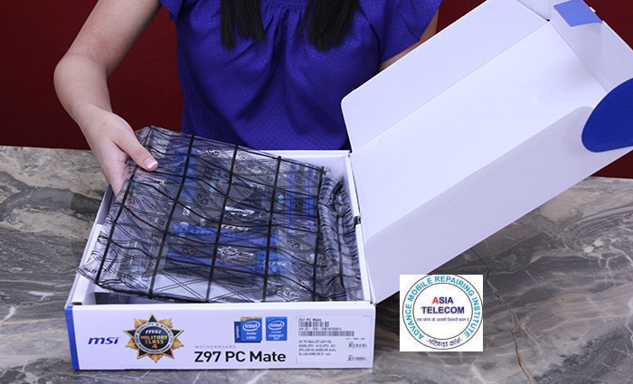
Take the motherboard out of its protective bag and place it on top of its box (a perfect non-conductive workspace which is the right size to fit the motherboard on). Do not place the motherboard on the anti-static bag it was in - although most commonly used designs for bags are not conductive this is not a good work surface and you are better off just using the box as the bag only offers protection when parts are inside of it.

Lift the CPU retention bracket lever from underneath its latch by pushing down and out away from the cpu socket. Bear in mind that depending on the socket of your motherboard, this may vary slightly and referring to the manual that came with the motherboard is advisable.


Unbox your CPU at this stage and remove it from the protective moulded plastic, holding it carefully by the edges


Now proceeds the most nerve racking part of the build. Lift the CPU retention bracket lever to reveal the socket and its pins. These are incredibly delicate and easy to bend (which motherboard manufacturers will not accept an RMA for), so be very careful when working around the socket.


If your protective plastic socket cover is located on the inside of the retention bracket, you may need to remove the protective plastic cover which was over the socket at this stage. With our motherboard the protective cover is on the outside of the bracket so will pop off when securing the CPU into the socket.
Gently lower the bracket over the CPU, sliding it onto the raised pillar on the motherboard.

Push down the retention bracket arm and hook it back under the latch where it was originally. This may take some force, and may even cause some rather worrying noises, however if you have placed the CPU in the correct position in the socket no harm will be done and this process ensures that the CPU is in proper contact with the socket. This is an area where more detailed video guides can be watched for reassurance that you are doing the right thing and applying a normal amount of force if you are particularly worried about this step

The protective cover will pop off as you lower the lever. Be sure to keep this in a safe place, as you will need this if you have to send your motherboard back to the manufacturer to protect the socket during shipping. Your CPU is now installed into the motherboard.


CPU Cooler Installation
If you are using an Intel stock cooler (one which is bundled in the box with the CPU) remove it from the packaging and place the pins in the corners through the holes surrounding the CPU socket (ensuring that the pins at the corners are rotated to an unlocked position by rotating the top of them in the direction of the arrows). After this, turn the top of the pins in the opposite direction to that shown by the arrows to lock it in place. You can check that it is seated correctly by attempting to gently twist it - there should not be any significant movement. Be sure to arrange the fan cable so it doesn’t interfere with the spinning of the fan.
If you are using an aftermarket cooler there are a vast array of different mounting mechanisms and so you will need to follow the instructions provided with it ensuring that you use the correct mounting hardware and applying thermal paste as a BB sized ball in the centre of the CPU if necessary. Some CPU coolers, similarly to stock CPU coolers, have thermal paste pre-printed to the underside for easy application (this is frequently the case for closed loop coolers)


Plug the 4pin PWM fan connector on the end of the wire coming from your CPU fan into the CPU_FAN header on your motherboard at this stage if you wish (we actually forgot about this until the build was already in the case). Watch that the cable isn’t in the way of the fan blade!
RAM Installation
As the final part of this sub-assembly we will be installing the RAM into the motherboard. Read the motherboard manual to find out which slots you should be using for the number of sticks of RAM you have (they are usually color coded and so can be easily referenced). We will be populating all the slots in our build. First, pull back the clips on either side of the RAM slots you are going to use

Notice the clear off-centre notch at a point both on the slot and the RAM stick to indicate which way round the sticks should be placed and ensure they can only be placed one way
Note that in the picture below the RAM is being held by the edges. Avoid touching the gold contacts along the bottom edge of the RAM


Place each RAM stick in a slot and push down evenly on both sides until the clips engage


At this point in the build, if you have integrated graphics you can attempt to power on the build outside of the case by connecting the power supply 20/20/24 pin ATX and 4/8pin EPS connectors and shorting out the PW_SWITCH pins on the front panel headers by touching a conductive screwdriver or paperclip to them for a split second or connecting the actual case switch to power the build on.
Installing the Motherboard in the Case
We can now move this sub-assembly into the case

Best part about having a side panel window is peeling this off

You may need your screwdriver to loosen the thumb screws securing the side panels first of all - they are often very tight from the factory
Take off the case side panels


Find the box containing your screws and other accessories which are bundled with the case (it is usually located in a 3.5" drive bay) and find the standoffs for your case. These sit between your motherboard and the screw in order to stop the motherboard touching and shorting out on the case and are vitally important. In our case, the standoffs were pre-installed for an ATX motherboard. It is a relatively painless process, if they are not, to go through screwing the standoffs into the case in the locations where your motherboard has a matching hole for a screw.
DO NOT FORGET THE STANDOFFS. To repeat, our case had standoffs pre-installed for an ATX motherboard and so this step was not required. Otherwise you will need to screw the standoffs into the motherboard tray and the screws into that to offset the motherboard from the case and prevent it from shorting out.


Next we need to install the motherboard I/O shield. This is a metal panel which covers the gaps between your motherboard I/O connectors in the cutout at the back of the case. Ensure this is the correct way round (engraved labels facing to the outside of the case and the right way up to match the connectors on the motherboard). This is a time when a lot of builders make their blood sacrifice to their machine on sharp edges, so take care! Place the metal panel into the gap at the back of the case and push firmly around the corners and outside edges until it clicks to secure it.


Now with standoffs in position and I/O panel placed we can take our motherboard and place it in the case. It is best to lie the case on its side as you do this.
Lower the motherboard into place. Line up the connectors with the gaps in the I/O panel and push the connectors into the panel before lowering it all the way onto the standoffs. You may need to apply some pressure in the direction of the back of the case to line up the screw holes with the standoffs - this is normal and is the I/O panel resisting the connectors. However be sure that none of the metal tabs from the panel are making contact with the inside of the connectors after the process.


0 comments: